Stage Options
GIS Image
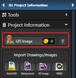 GIS Image: Insert high-resolution aerial imagery along with surveyed terrain data of your client’s property.
Type in the property address and aerial images will be inserted directly into your Vip3D project. This makes it possible to automatically generate 3D terrain, trace existing structures, and calculate access.
For more information, see GIS Aerial Imagery.
Import Drawings/Images
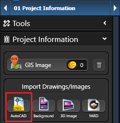 AutoCAD Drawing: Import Information from an AutoCAD® File into a Vip3D Project. Information from DWG files, the native file format for Autodesk’s AutoCAD software, can be copied directly into Vip3D projects.
Vip3D can also import information from DXF files. This makes it possible to import templates, landscaping symbols, and whole 2D design projects into Vip3D.
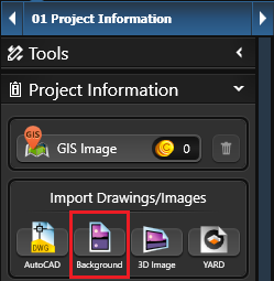 Background Image: Insert plot plans and blueprints as background images to trace objects into Vip3D. Using the Background Image feature, you may trace existing structures and hardscapes from a plot plan of your project.
You may use printouts, sketches, blueprints, or any other graphic file as a background image. The image may be in the .bmp, .jpg, .png, .tga, or .tif graphic files formats.
For more information, see Background Image.
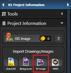
3D Image: Insert and edit photos for 3D presentations. Vip3D makes it easy to design a project using a photo of the property.
Use a photo, such as a picture of the client’s house, as a backdrop to a design or as the basis of the design itself.
With this feature, you can take a picture with your smartphone and upload the image directly to Vip3D for editing.
For more information, see 3D Image.
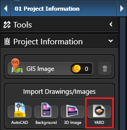 YARD Design (Vip3D Only): Import a project from YARD into a Vip3D Project.
NOTE: Only drawn objects can be exported from YARD. Inserted library objects, or designs originally drawn in Vip3D, will no longer be editable or identifiable if exported back into Vip3D; after being imported, designs become one static object that cannot be edited in YARD.
For more information, see YARD.
Property Line
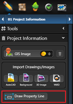 Draw Property Line: In 2D, create a Property Line that displays bearing and distance. Left click on the Property Line button to start drawing. Drawing should be done in a clockwise direction, as bearing is effected by the direction the line is drawn. Property Lines can be created with the Line and Arc tools.
Property Lines will automatically display distance and bearing in Construction Markup and Page Layout. Smart Data will provide Perimeter for all Property Lines as well as Area and Acres for completed Property Lines.
You can also display the Property Line in 3D.
Note: The bearing of the Property Line will change based on the Orientation, so we recommend setting the orientation first.
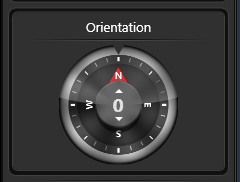 Orientation
Use the compass to set North for the project. As you move the sun or adjust the time, it will reflect the real life location of the sun.
In Construction Page Layout, the North Symbol will automatically match the Orientation set here.
Environment: The Environment options will set different backdrops in the distance of your project while in 3D and Presentation.
Left click on the drop-down menu to select the option you want:
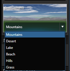
Mountains will show a mountain landscape.
Desert will show a desert mountain landscape.
Lake will show water with rolling hills along the horizon.
Beach will show water along the horizon.
Hills will show rolling green hills.
Grass will show an expanse of terrain.
NOTE: The Backgrounds are set and cannot be rotated or altered.