World Size & Environment
 Set the world size for your project. Left click the drop-down menu to choose the grid dimensions that work best for your design—up to a maximum of 2550 ft x 2550 ft. The default world size is 850 ft x 850 ft.
 Choose the distant backdrop for your project in 3D and Presentation modes. Backgrounds are fixed and cannot be rotated or edited. Left click the drop-down menu and select the background you want:
Beach will show water along the horizon
Coastal will show water along the horizon
Oceanfront will show water surrounding the grid
Desert Mountains will show a desert mountain landscape
Grass will show an expanse of terrain
Hill Options will show rolling green hills
Lake will show water with rolling hills along the horizon
Mountain Options will show a mountain landscape
GIS Data
Insert high-resolution aerial imagery together with surveyed terrain data, automatically created parcel lines, setbacks, 3D structures, and assessor property details.
 All of this is seamlessly integrated to help you quickly understand key site details as you begin your design.
Enter the property address and the data is placed directly into your project, making it easy to calculate access.
For more information, see GIS Data.
Background Image
Insert plot plans and blueprints as background images. With the Background Image feature, you can accurately trace existing structures and hardscapes directly from your project’s plot plan.

You can use printouts, sketches, blueprints, or any other graphic file as a background image. Supported formats include .bmp, .jpg, .png, .tga, and .tif.
For more information, see Background Image.
Import Drawings/Images
 AutoCAD Drawing: Import data from an AutoCAD® file. Details from DWG files, the native format for Autodesk AutoCAD, can be brought directly into your projects.
You can also bring in data from DXF files, allowing you to import templates, landscape symbols, and complete 2D design projects.
For more information, see Importing AutoCAD Files.

3D Image: Insert and edit photos for 3D presentations. This makes it easy to design a project using a photo of the property.
Use a photo—such as a picture of your client’s house—as the backdrop for a design or as the foundation of the design itself.
You can snap a photo with your smartphone and upload it directly into the software for editing. For more information, see 3D Image.
 YARD Design (Vip3D Only): Import a project from YARD into a Vip3D Project.
NOTE: Only drawn objects can be exported from YARD. Inserted library items or designs originally created in Vip3D will no longer be editable or individually identifiable if they are exported back into Vip3D; once imported, the design becomes a single static object that cannot be modified in YARD.
For more information, see YARD.
Property Line

In 2D, create a Property Line that automatically displays both bearing and distance.
Draw Property Line: Left click the Property Line button to begin drawing. Draw in a clockwise direction, as the bearing depends on the direction of each segment. You can create Property Lines using the Line, Arc, Outline, and Divide tools.
Property Lines automatically show distance and bearing in both Construction Markup and Page Layout. Smart Data also reports the perimeter for every Property Line, plus area and acres for any closed Property Line.
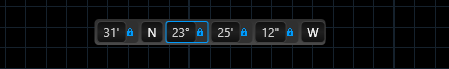
You can also enter an exact Distance and Bearing for your property line.
Flip: After you draw or input the line, you’ll have the option to flip the N/S or E/W direction of each side.
Setback: Once you draw a closed Property Line, the Setback control becomes available.
Entering a setback value applies the same offset to all four sides. To assign different setbacks to individual sides, left click the midpoint of the side you want to edit.

Note: Since Property Line bearings are calculated from the project Orientation, we recommend setting the Orientation first.
Orientation

Use the orientation compass to set North for your project.
Once North is set, moving the sun or adjusting the time will align its position with the real-world sun.
In Construction Page Layout, the North symbol will automatically follow the Orientation you set here.
