
Add Block
Add a block by choosing an option from the Insert Block drop-down list.
Choose the specific type of block you want to add—such as a 2D View, 3D View, image, logo, text table, Smart Data Block, or one of the available legends.
After inserting a new block, you can reposition it using the Move tool.
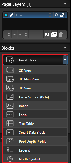
2D View: The 2D View creates a 2D view of your design. The shapes generated in the 2D View cannot be edited or selected. Select 2D View, then click OK to open the 2D Drawing Options dialog box.
In this dialog box, choose which Construction Markup layers to display in the 2D view. Select or clear the layers you want to show or hide. To print a grid with your 2D view, select Print Grid and set the Grid Spacing. You can also customize the symbol style for each 2D view.
3D Plan View: The 3D Plan View creates a top-down, scaled 3D representation of your design for full-color construction plans. Use the Hide/Unhide Menu to choose which layers to display. After configuring the 3D Plan View, lock the visibility in the Panel so future changes to the Hide/Unhide Menu do not affect the inserted view. This allows you to create multiple 3D Plan Views with different layer combinations.
3D View: The 3D View inserts a locked 3D view of your project. Locations created in Photo Mode appear as preset angles when you insert the 3D View. Unlike a screenshot, the view remains adjustable after insertion.
Double-click the 3D View to adjust its angle. Use the left mouse button or arrow keys to rotate the view, the right mouse button to zoom in and out, and the center mouse button to pan. To adjust the time of day, hold CTRL while pressing the arrow keys, or press N. After configuring the 3D View, lock the visibility in the Panel so future changes to the Hide/Unhide Menu do not affect the inserted view. This allows you to create multiple 3D Views with different layer combinations.
Cross Section: The Cross Section view cuts through your project along a precise plane to reveal the details you need. When the section plane is active, everything on one side of the cut is hidden, helping you focus on the relevant details. Visit Cross Section to learn more.
Image: Add images of your design or other elements, such as company logos, by selecting the Image option. A file selection window opens, where you can choose a BMP, PNG, JPG, TGA, or PDF file to add to your layout.
Logo: Add your logo by selecting the Logo option. If a logo is already listed on the Project Information screen, it is selected automatically. If no logo is available, a file selection window opens. Select a BMP, PNG, JPG, or TGA file to add the logo to your layout. The new logo is also added automatically to the Project Information screen.
Text Table: Add a text table to your construction sheets. Choose the number of columns and rows, then drag a corner handle to resize the table to fit the page.
To add rows or columns, select a cell in the Text Table and click the three dots.
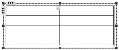
To edit individual cell borders, click the up arrow and select the borders you want to modify. Adjust the selected borders on the Line tab under Object Styles.
To merge cells, hold Shift and click the additional cells you want to select. Click the up arrow, then select Merge Cells. To separate merged cells, select the merged cell, click the up arrow, and select Unmerge Cells.
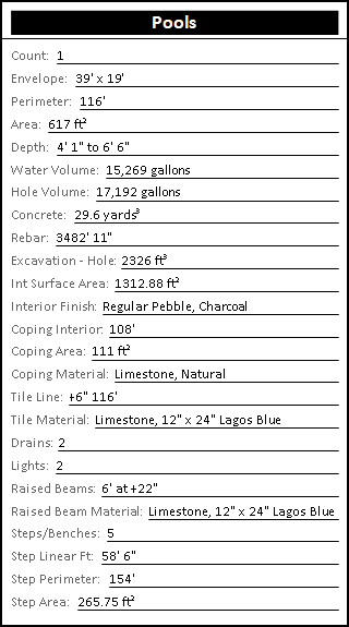
Smart Data Block (Vip3D Only): The Smart Data Block allows you to display automatic detailed calculations for your projects. This includes Turn Downs, Step Risers, Dirt Displacement, Concrete Yardage, Rebar, and more. When you create the block you can choose which types of data will be displayed. Visit Smart Data in Construction to learn more.
NOTE: Smart Data Blocks update automatically as you make changes to your design.
Pool Depth Profile (Pool Studio and Vip3D Only): The Pool Depth Profile creates a copy of the pool depth profile.
Plant Legend: The Plant Legend allows you to automatically display a symbol legend listing plants and trees inserted into your design.
Item Legend: The Item Legend allows you to automatically display a symbol legend listing library items inserted into your design. This allows you to create separate legends for items, lighting, and irrigation.
Line Style Legend: The Line Style Legend allows you to automatically display the Line styles and assigned category.
Fill Style Legend: The Fill Style Legend allows you to automatically display the fill styles and assigned category.
Markup Symbol Legend: The Markup Symbol Legend allows you to automatically display markup symbols, quantity and name of symbol.
NOTE: All legends update automatically as you make changes to your design.
North Symbol: The North Symbol will automatically match the Orientation set in Stage 1: Project Information. To add a custom North Symbol, create the symbol in Construction Markup and save as a template to the Symbols > North Symbols category.
Settings
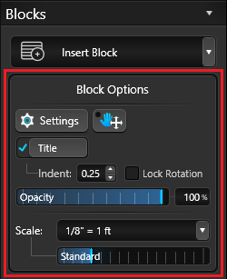 The Object Settings button allows you to change settings of an inserted object. Once the object is selected, click the Settings button.
You can edit 2D Views, 3D Plan Views, 3D Views, Cross Sections, Images, Text Tables, Smart Data Blocks, Plant Legends, Item Legends, Line Style Legends, Fill Style Legends and Markup Symbol Legends.
Edit 2D Views
The 2D View Settings box will come up and display a list of your markup categories. You select the Categories you would like to appear and can change other properties of the object.
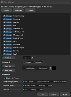 Markup Category Options:
- If the box next to the Category displays a Markup Pencil, it will use the Hide/Unhide settings from the previous stages.
- If the box displays an Eye, everything on that layer will appear.
- If the box displays Hide All, everything on that layer will be hidden.
Background Options:
- Select Opaque to have a solid white background. Select Transparent to have remove the white background so the entire view inside the border is transparent.
Scale Options:
- Show Scale Bar (Vip3D Only): When checked, a Scale bar for the 2D View will be displayed in the bottom right.
- Show Scale Ratio: When checked, the Scale for the 2D View will be displayed in the bottom right. Use the Font controls to the adjust the appearance of the Scale.
- Lock Rotation: When checked, the scale bar and ratio will remain locked in the bottom right corner when the 2D View is rotated.
- Background: When checked, the scale bar and ratio have a white background.
Fill Patterns Options:
- Display Fill Patterns: When checked, fill patterns will be displayed.
- Also set the appearance for Landscaping Symbols, Wooden Decks and Pergolas.
Press the Ok button when done.
Edit Legends
The Plant Legend displays the symbol, quantity, common name, botanical name, and container size for plants and trees inserted into the design.
Changes to the Design: The legend lists the actual items inserted into your design. If changes are made to the design, the legend will automatically update item quantity and remove items that have been deleted.
Use Hide/Unhide Settings to Calculate Quantity: With this box checked, the Legend does not display plants/trees hidden in earlier stages.
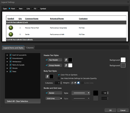
Manual Changes to the Legend: The information listed on the legend may also be changed manually. Simply left click on the item and it will become a text field you can edit. This allows you to enter the common names you use or change the quantity to reflect actual build amounts.
